As the students return to Carleton and campus life resumes in earnest, you may notice some changes in the IdeaLab and the AT offices in the Weitz Center for Creativity (not to mention the massive construction project just outside…). The IdeaLab has been undergoing renovations and redesigns to better serve the whole community. We’ll be writing another post about that whole process, but for this post I’ll be focusing on one of our newest tools: our 3D printer. This post will also focus primarily on our initial prints, rather than how-tos, but those will also be coming in the future.
After a lot of consideration, talking with experts, and looking at samples, we decided to go with an Ultimaker2+, one of the most highly-regarded 3D printers on the market. It’s a very dependable, well-supported machine, and looks fantastic too.
As part of the initial set-up, we needed to calibrate and configure the machine. This took a few hours, as the build plate (the section that the 3D printer prints onto) needs to be perfectly level. This level of specificity goes beyond the standard bubble level; we were dealing with differences in size of less than the thickness of a piece of computer paper. With our filament loaded and the plate leveled, we printed our first test print: a little robot designed by Ultimaker.
After that success, Andrew had me get a large file off of Thingiverse to print. Thingiverse is an online community where people upload 3D files for others to download, modify, and print. It can be a rabbithole for time, as there is so much incredible content available to browse and look through. I ended up choosing an owl pen holder. You can see it on Thingiverse by clicking here. This was addicting to watch the 3D printer layer up piece by piece, so we set up our timelapse camera to shoot the print. Check it out below! (For reference, this five-inch-tall owl took about 27 hours to print, as each layer is less than the width of a human hair in thickness.)
Here’s what the final product looks like. It’s surprisingly sturdy and solid.
Earlier this month, we were part of the ITS team that organized a major piece of the All Staff Retreat. Because this year was the tenth anniversary of the first staff retreat, the theme revolved around looking ten years back (to 2005, and ten ten years into the future (to 2025). As technology is a very visible indicator of change and progress, ITS was asked to prepare some activities that would help show what would be coming in the future. Although we focused on a variety of differences between the past, present, and future, our activities reflected two main changes: the rise of social media over the past ten years and the impending rise of Virtual Reality over the next ten years. Our social media activity involved pre-installing social media apps onto iPads for groups at each of the tables to share how they use social media and what apps they enjoy using. For exploring virtual reality, we put together Google Cardboard units and had ITS staff trained in how to use them. We’ll explore each of these activities a little more below, but start by discussing the preparations that went into the Google Cardboard activity.
About Google Cardboard
To understand the activity, it’s also important to understand what Google Cardboard is. Essentially, it’s a piece of a piece of cleverly folded cardboard with two plastic lenses that will hold a smartphone. This creates a low-cost, decent-quality virtual reality viewer. It’s particularly clever because it uses the phone for processing power, screens, gyroscopes, and storage of virtual reality applications, instead of making the user pay for those separately.
Google Cardboard (Image from Slashgear.com)
How exactly does Google Cardboard work?The effect is very similar to how one’s eyes work. Essentially, the smartphone takes a single image, and then splits into two slightly different images that are then distorted a bit. When viewed through the Google Cardboard lenses, these two images merge into one immersive image. It takes this trick a step further by using the motion-sensing gyroscopes within the smartphone to match how the phone moves. This allows one to turn around and look up and down, furthering the feeling of “immersion” in the experience.
There are a variety of apps and experiences that are possible with Google Cardboard. We built a page that explores the basic apps to get, as well as which cardboard units we bought for the presentation. You can find it by clicking here. We highly recommend starting with the Google Cardboard app.
Preparations Part I: ITS Meeting
Part of the experience of Google Cardboard is the fun and cool-factor of assembling it from the flat cardboard sheet. We originally wanted to give the full staff meeting a chance to try it out themselves, but decided to do a dry run with the All ITS meeting first. This turned out to be a good idea, because the Cardboard units proved a little more confusing than we had expected, and took more time to assemble. While the ITS staff had a fun time assembling the units, they thought the experience of actually trying out the units was much more rewarding, so we decided to pre-assemble most of the units.
Building the Cardboard Units
With around fifty cardboard units to build, we knew we had some work ahead of us. Luckily, with some helpful student workers and assembly line style work, we managed to get the units put together in no time! The units were very straightforward to assemble. We put together the lens-holding piece, folded the body over it, and installed the velcro pieces on the flap that holds the phone. As a final touch, we added a sticker featuring the ITS logo to each unit to help them all look uniform. Check out the stack of finished units below!
While we had assembled the Cardboard units, we wanted to make sure that everyone at the retreat understood how simple and doable it was to assemble one of these units. We produced the timelapse video below to show the full assembly of a Google Cardboard unit.
The Main Event: Staff Retreat 2015
Staff Retreat was a success, with many teams of people (including ITS) working to create a great experience for everyone who attended. The main speaker, Tracy Knofla, was the speaker at the first staff retreat ten years ago and the Retreat Committee brought her back to mark the ten year anniversary. We began with a great icebreaker that would’ve proved difficult ten years ago: take a selfie with as many people as possible, and if you aren’t able to take a selfie, photo-bomb as many people as possible.
As ITS, we followed with a look at what’s changed at Carleton and in the world in the past ten years in a presentation by Janet Scannell. This transitioned into a presentation on Google Cardboard by Troy Barkmeier and Eric Mistry. We then had ITS members stationed at each of the tables to introduce their colleagues to Google Cardboard, Virtual Reality (VR), and social media apps. We had had the ITS activity leaders pre-download apps and VR videos to their phones, so they were able to get the groups started immediately. It was a collaborative and engaging effort to introduce our staff to an accessible, affordable future technology. As we said in our presentation:
Now obviously, this isn’t a super sophisticated or comfortable object, but it allows anyone with a smartphone to cheaply and easily try out virtual reality. We think you’ll really enjoy the magic this simple tool creates. You’ll be travel the foot of the Eiffel Tower and look around, immerse yourself in the opening song of the Lion King Musical, or investigate a New York Times story even closer.
In addition to our VR activity, we had a variety of other activities. As previously mentioned, we had iPads on every table preloaded with a variety of social media apps (thanks Randy Hoffner!) that would allow those who weren’t actively using the Google Cardboard to explore and show each other their favorite social media apps. We also had some great side tables featuring other technologies. Ann from the Library brought great information and demos on the Library’s new Overdrive eBook system; Mark from Physics had a 3D printer that can make nearly anything imaginable; Wei-Hsin showed the world with Google Earth and GIS; and Eric from communications had an awesome high-end drone to check out. Matching the theme of the Retreat, Troy assembled a “Museum of 2005” that featured the technology used in 2005, from an iPod Classic, to an older iMac, to the famed Motorola Razr.
In all, we found that the activities were high energy and engaging for all the attendees. Thanks to the great team spirit of ITS and the other organizers and volunteers, we created an exciting experience with a positive vision towards the future. Here are some pictures from the event! (More on the original post)
Every day of my Carleton job has been a new adventure. I get opportunities to work on creative, innovative projects that I get to run fairly autonomously. In this post, I’ll be talking about the Lightboard.
The Lightboard was one of the first projects I was assigned to during my starting week at Carleton. I was given the following problem: research other Lightboards around the country, and try to figure out how to make ours work well. Before we delve into solving the problem, I should probably answer the most obvious question: what is a Lightboard?
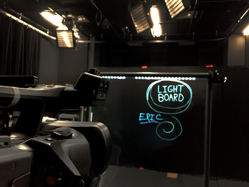
A lightboard is, in essence, a clear whiteboard. The instructor stands on one side of it and writes on it with a fluorescent marker. A camera is on the other side that captures the writing that glows on the screen. The footage is then flipped, cropped, and edited for color and lighting. We end up with footage that captures not only what the instructors are writing, but also their full expressions and face, rather than their back or hands.
This is our basic Lightboard setup (This was pre-wiring of the Lightboard)
The original Lightboard was developed at Northwestern by Michael Peshkin, a professor of Physics. His site not only shows his (very sophisticated) Lightboard build, but collects build instructions and documentation from Lightboards at schools around the world. This was extremely helpful in figuring out how to solve our own issues with the Lightboard.
With that brief introduction, back to the problem at hand. We already had a frame with plexiglass installed, but it was nearly impossible to capture what was being written on the board, and the audio was also muffled. The audio problem was relatively easy to solve; we simply attach a wireless lavolier microphone to the presenter, and the audio streams directly to the camera, instead of having to go through the plexiglass. Solving the visual issues was a bit more of a process. First of all, the plexiglass was extremely reflective, and our first attempts often captured more of the camera than the presenter. Second, if the presenter was well-lit enough to see, it meant that any writing was impossible to see. This was what an early test looked like.
Idea 1: Adding lights to the board surface.
First, I attempted to add better lighting to the outside of board. This was simple enough. I had bought some simple IKEA lights [link] to install in my apartment bookshelves, and figured they might help light the surface of the board, as they were relatively flat and easy to place where I wanted. I stuck them on the front of the plexiglass and angled them down, hoping that it would help make both the markers and the presenter more visible. It did help, but not in the right way. Even with fluorescent markers, the writing was barely distinguishable.
Next, I tried adding blacklights to the board. My reasoning was that backlights help things glow, and that it would really boost the intensity of the fluorescent markers. Spoiler alert: It didn’t work. Even with the blacklight, the markers barely glowed. At this point, it became pretty clear that attaching any manner of lights to the surface of the board was not going to work.
Idea 2: Installing lights directly to the side of the plexiglass.
After studying the documentation and other builds more closely, I decided to test what happened when I added lights directly on the edge of plexiglass. I borrowed a spare piece of plexiglass and attached the lights on the edge facing inward. The entire piece glowed as the plexiglass conducted the light from edge to edge. I mounted that piece onto our existing board and did a side by side comparison. The difference, as you can see in the videos below, is very apparent.
With the difference made clear, I got permission from Ben at St. Olaf to physically modify the board so I could install the lighting properly on the top edge of the unit. I removed the top piece and a few support pieces and began to get to work. I lucked out and found that this board had a grove that would perfectly fit the IKEA lights. I installed the lights, remounted the top piece, and added a power strip to the board’s base. The change in quality was fantastic.
Better lighting and editing
With the board now effectively lit, I got to focus on lighting and editing the footage. With lighting, I’ve found that placing a light on both sides of the board to gently light the presenter works quite well. It can’t be too focused, or it creates jarring dramatic shadows. It also can’t be too diffuse, or the board begins to have reflection issues. We also shoot in an otherwise dark studio, with a black background behind the presenter. We use a polarizing filter on our tripod-mounted camera to further reduce reflections, and also cover the red “recording” light with painters tape to ensure it does not reflect on the board.
After we’ve shot the footage, it goes through a brief editing process. I use Adobe Premiere to edit, but the necessary changes would likely be possible on less expensive or free software. I start by color correcting the video, then super-saturating the specific blue of the marker we use to make it extra-visible on the final product. I then apply mirror image filter (called horizontal flip in Premiere) so the writing is facing the proper way, and crop and scale the video so that we only see the board, and not any of the lights or frame. The video is then exported and sent to the presenter for their class or presentations.
We’ve had some really interesting uses so far, even in this initial experimental stage. One of my favorites has been Japanese symbol lessons developed by visiting Professor Miaki Habuka. She has her TA go over the symbols that students in her Intermediate Japanese class need to learn. By using the Lightboard, her students are able to see each stroke of the symbols as they are written, which is an important component in understanding how to properly write in Japanese. Check out the video below to see an example of one of the language lessons. This is just one of the many uses for the Lightboard, and we’re looking forward to many more amazing projects to come.
This is just the beginning of the Lightboard. In later posts, I’m planning to write a more in-depth guide to our specific build with pricing, instructions, and advice. I’ll also continue to show more examples of finished videos and additional modifications or builds.